In our previous posts from June and December we have shone light on the optical detection of wires and wire harnesses. However, all these algorithms are based on camera images and return the poses of desired objects in the sensor’s coordinate frame. To incorporate these information a calibration of both sensors, as well as the robotic manipulator is necessary. The fully autonomous calibration pipeline developed at TUM resolves this issue.
We distinguish between two types of sensors: Global sensor are 3D cameras, that are statically positioned in the robot’s environment and are constantly watching the same view angle. They are useful to obtain information about changes of the environment itself, e.g. whether the supply consumable items of has been restocked or a human is approaching the robot. Also they may be used to locate regions of interest (RoI).
In contrast there are local sensors, which are mounted in an eye-in-hand configuration. Usually these sensors are used to provide the input for robotic manipulation tasks, i.e. the position of objects or parts of objects. As such, these sensors tend to be way more precise but cover less view range. Thus the robot will have to position them at a suitable view angle to take closer looks on RoIs.
The calibration of both sensor types, as well as the manipulator itself can be computed by the help of the Iterative Closest Point (ICP) algorithm. In it’s basic from the ICP algorithm is used to merge two overlapping point clouds. It is however hard to apply to fuse recordings from static sensors that have heavily distinct view angles, as the potential overlap is too small. As such the REMODEL calibration pipeline is based on an object centric calibration approach. By training a Deep Neural Network we can detect the robotic manipulator in the recorded point clouds and even predict the missing, occluded points. Finally the reconstructed model can be used as an input to the ICP algorithm to detect the relative camera post to the manipulator.
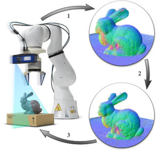
Figure: Steps of the local sensor calibration procedure: 1) A robot with an attached 3D sensor captures multiple recordings of an arbitrary scene by moving the eye-in-hand sensor. 2) ICP based bundle adjustment is used to undistort and align the point clouds by optimizing the robot’s kinematic model. Note how the crispness improves on the bunny’s ear and crib. 3) The obtained calibration parameters are uploaded to the robot manipulator.
For local sensors the calibration pipeline is based on a slightly different assumption: Whenever the robot moves the sensor and points it to a different view angle, the overlapping surfaces between both point clouds must be the same. Hence, all offsets between those surfaces must originate from errors in the sensor pose and thus from an imperfect kinematic model of the robot. We thus extended the ICP algorithm to perform bundle adjustment on a number of different 3D recordings, to compute the optimal kinematic parameters.
For more information please check the publications below:
Bare Luka Žagar, Ekim Yurtsever, Arne Peters, Alois C. Knoll, “Point Cloud Registration with Object-Centric Alignment,”, in IEEE Access, 2022, doi: 10.1109/ACCESS.2022.3191352.
Arne Peters, “Robot Self-Calibration Using Actuated 3D Sensors”, arXiv, 2022, preprint, doi: 10.48550/arXiv.2206.03430
Written by TUM